Tri-Offset Butterfly Valve
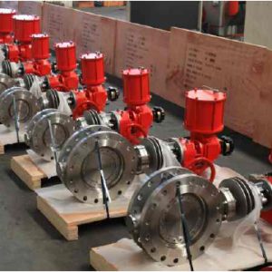
BUTTERFLY VALVE
Tri-Offset Butterfly Valve
Design Feature

Laminated Disc Seal
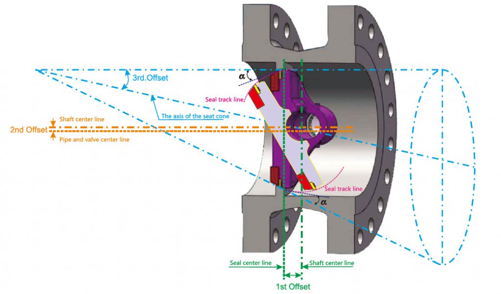
Laminated sealing is mounted in the disc, easily for maintenance and replacement. It consists of 3~5 flexible graphite or PTFE layers self adhere with fine machined stainless seal ring.no need traditional phenol resin adhere joint, There is a reasonable clearance between disc seal and disc, provide a floating resilient seal and self centering tight seal both in low & high temperature application. Conical angle & streamline profile of this laminated disc is optimized by computer finite element analysis to eliminate any potential jamming as well as give a greater Cv.
Anti-blowout shaft
Internally & Externally retained, double times blowout proof stem design per API 609.
Internal: Lower end shaft is grooved with Hemicycle Ring, prevent stem blowout.
External: Shaft is designed with an integral collar and was blowout prevented by gland follower.
Anti-blowout shaft
SUNGO triple offset butterfly valves are all metal construction and sealing, it is inherently fire safe design. Fire safe tests to API 607 were successfully performed in SUNGO Research & Development laboratory.
Anti-blowout shaft
SUNGO standard emission control is 20 PPM
a. ) Shaft is fully guided by shaft bearing & gland follower to avoid
any side jiggle due to line pressure thrust.
b. ) The packing set is pre-compressed and is a combination braided graphite rings top and bottom with die formed flexible graphite rings between.
c. ) Controlled shaft & stuffing box finish with Ra0.4~Ra0.8 on
shaft and Ra3.2 on stuffing box which allow a bettor holding of packing ring and results in a better shaft sealing performance.
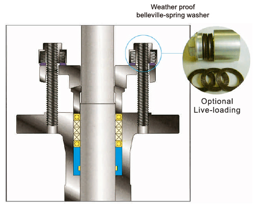
d. ) Optional Live Loaded gland flange Is available for providing
constant packing compresion to reduce fugitive emission from shaft seal.
e. ) Optional shaft seal design per Shell MESC 77/312 & TA-Luft is
also available upon request.
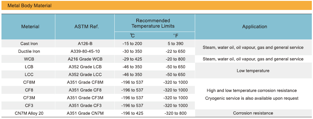
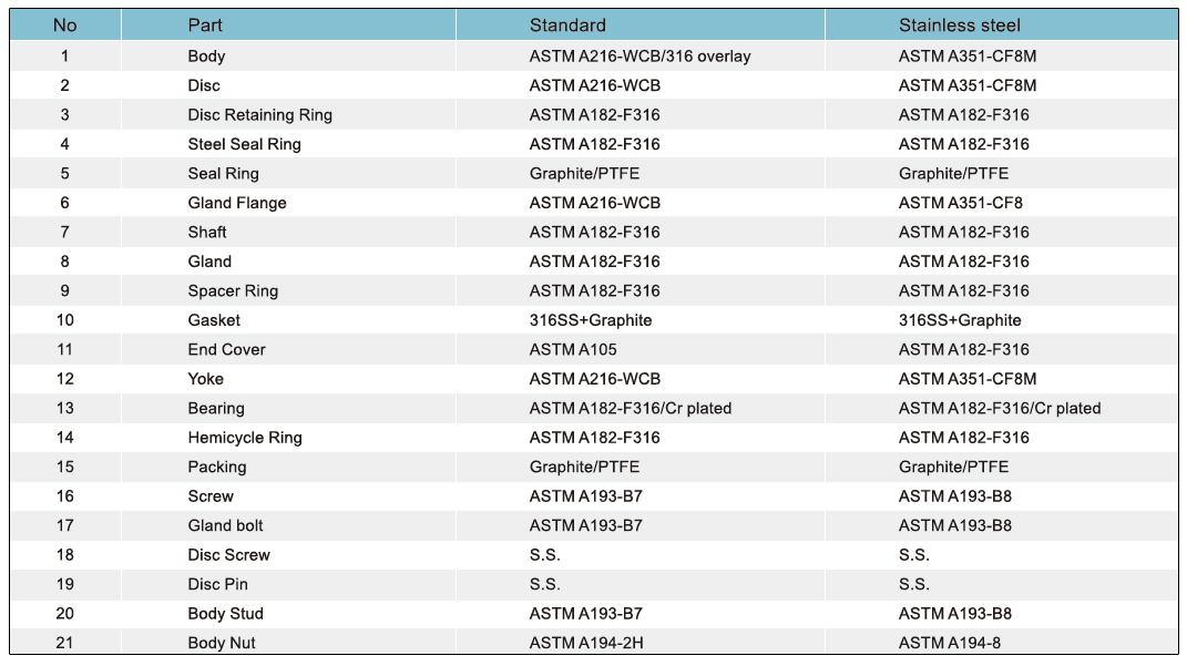
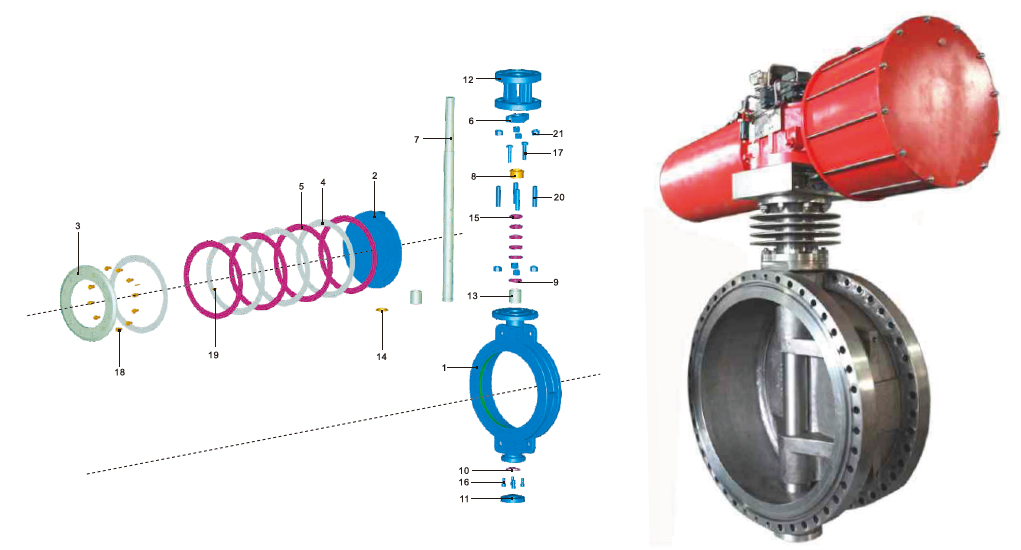
Material Specifications
Dimensions & Weights

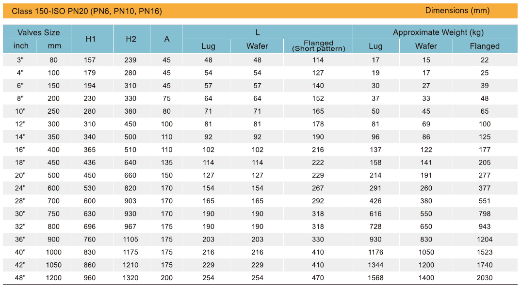
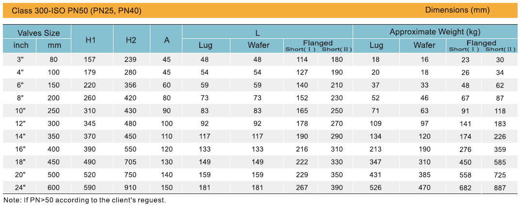
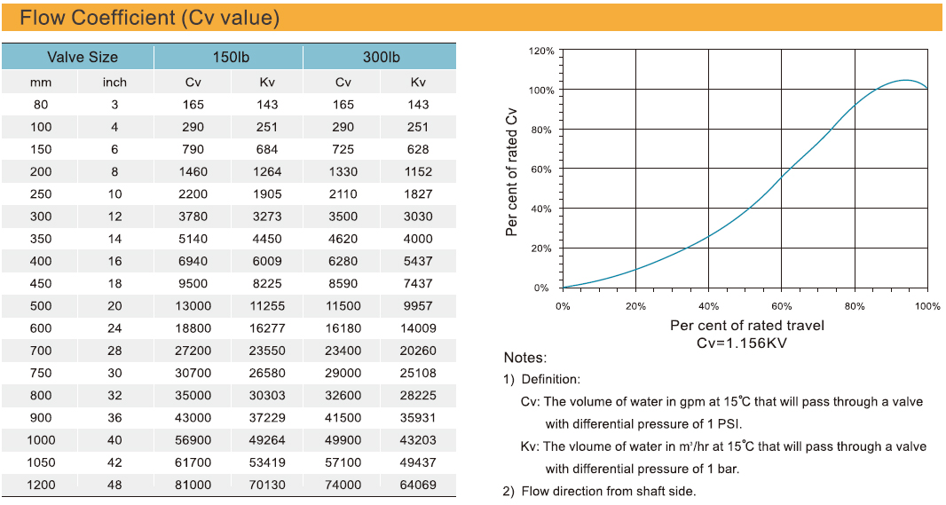
Engineering Data
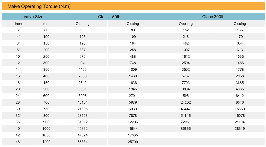
Notes:
1) Torque shown are based on normal temperature with flow direction from shaft side.
2) Torque shown in this table is to be used as a guide for actuator selection. A safety factor of 1.2~1.4 is recommended for actuator sizing.
3) Torque may be changed according to differedt medium and trim material.
4) The relationship between values are liner, therefore it can be interpolated between nominated values.
