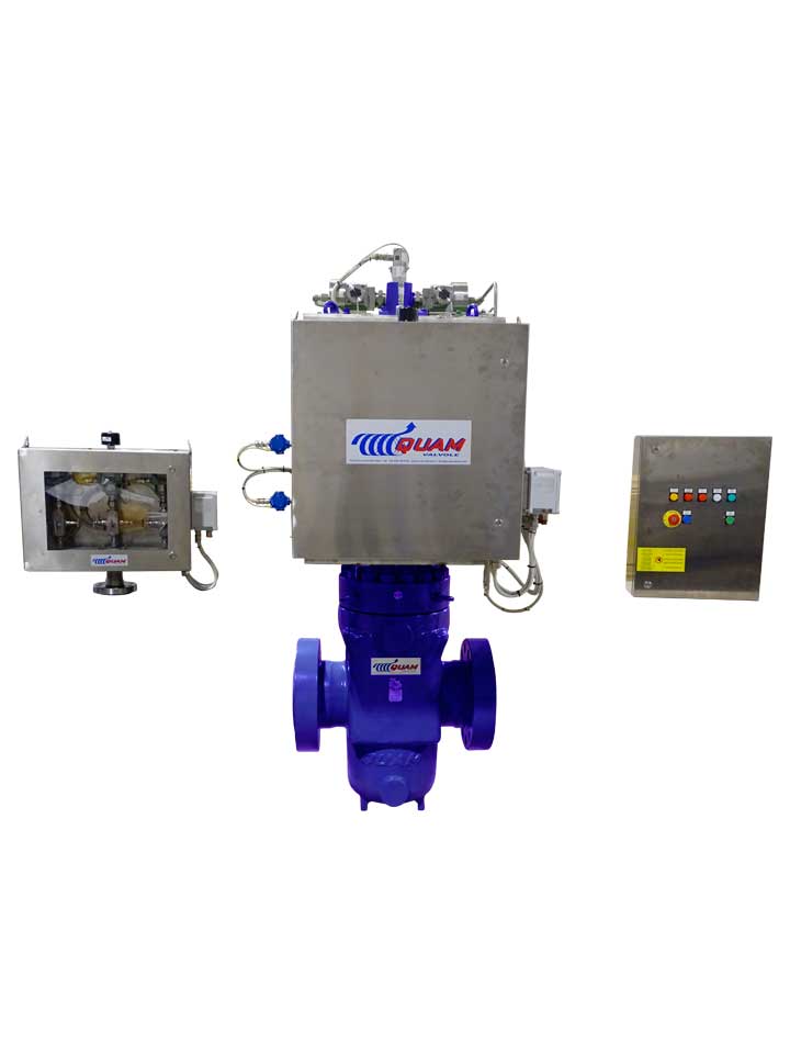
QUAM HIPPS ELECTRONIC SERIES

QUAM HIPPS ELECTRONIC SERIES
Description
The QUAM Electronic HIPPS is a SIL 3 Capable System, designed according to IEC 61508 and IEC 61511 standards, used to protect downstream equipment against overpressure or upset conditions coming from the Upstream.
General Application
QUAM Electronic HIPPS System considerably reduces overpressure process risks and environmental impacts with lower weight and cost for piping and vessels downstream the system itself.
No need to install relief devices.
QUAM serie: HIPPS Category: High Integrity Pressure Protection System Tags: HIPPS, Electronic Logic Solver, Initiators, SIL 3.
- Key Features
- Benefits
- System Architecture
- SIL Guide
- No need to install a by-pass line – QUAM Actuated Gate Valve is designed to be opened against full differential pressure
- Independent certification – 3rd party SIL3 certificate
- Tight Shut-off – Leakage requirements as per Class VI of ANSI/ FCI 70-2
- Fugitive Emission – In accordance with ISO 15848-2
- Fire Safe Design – Gate valve are tested to API 6FA
- Fast Action – Valve stroking time for safe action: less than 2 sec.
- Integrated Design – Any part of the safety system is internally designed and manufactured
- Single Source – For Valve, Actuator & Control System
- Better Sealing Feature – Of Slab Gates against Ball or Axial Flow
- Overall Dimensions – Smaller than other valve types
- Heavy Duty Design – For long life service
- Easy & Safe Maintenance
- 100% ITALIAN MANUFACTURING – QUAM Valves are Engineered and Manufactured entirely in Italy
- Electronic Logic Solver – Electronic Logic Solver detects signals from the Transmitters and closes the final element de-energizing the solenoid valves in order to discharge the power fluid from the cylinder by the quick exhaust valve, this action strokes the main valve to the safety position.
The solenoid valves are installed in series with suitable voting logic to achieve SIL3 requirement.
Partial stroke test is available for inspection upon request. - Initiators (Pressure Transmitters) – Pressure transmitters are configured 2oo3 voting logic and are engineered to detect the pipeline pressure and send analogic 4-20 mA signal to Logic Solver
- Final Element (Actuated Gate Valve) – The actuated gate valves close the downstream line and is usually configured in 1oo2 voting logic to achieve SIL3 requirement.
| SIL Safety Integrity Level | PFD (Avg. Probability of Dangerous Failure on Low Demand Mode) | PFH (Avg. Probability of Dangerous Failure on High Demand Mode) |
|---|---|---|
| SIL 1 | ≥10E-02 to <10E-01 | ≥10E-06 to <10E-05 |
| SIL 2 | ≥10E-03 to <10E-02 | ≥10E-07 to <10E-06 |
| SIL 3 | ≥10E-04 to <10E-03 | ≥10E-08 to <10E-07 |
| SIL 4 | ≥10E-05 to <10E-04 | ≥10E-09 to <10E-08 |
